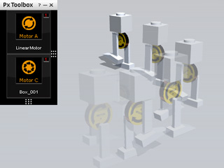
Using Segway with Eccentric Legs � Bipedal Robot
In the Moving with Motor - Segway section,
the movement behavior of the structure is mainly driven by the motor itself. However, if the motor is assembled with
physics-enabled legs that are constrained to the eccentric points of a motor, the structure can move as a
robot with two legs.
Creating Power Source with Motor
-
Apply an Infinite Plane from the Physics Props library to act as the surface for the robot to move along.
-
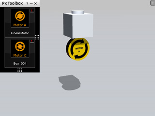
Create a segway first but lift it off the ground.
-
Upon simulation, the segway will fall to the floor and start to
move around.
Adding Legs with Off-Centered Joints
By using dummy props to act as bolts, you are able to add two legs that are driven by the motor which will touch the ground at different times to prevent the upper section from falling to the ground.
Holding the Robot Straight Up
-
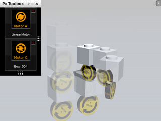
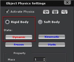
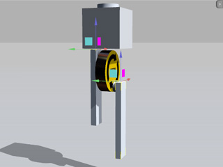
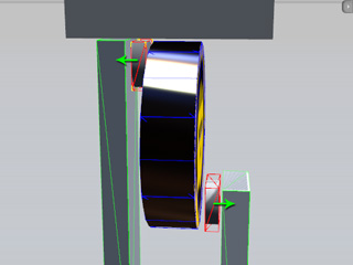
Apply two cylinders and move them to the positions besides the motor
as shown in the illustration below. Set the cylinders as Dynamic rigid body. They will be
used as bolts for connecting the motor and the legs.
|
|
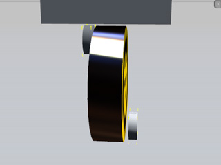
The two cylinders are assembled off-centered
-
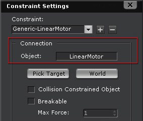
Select the two cylinders and apply Generic constraints to them. Pick the Motor as their target.
-
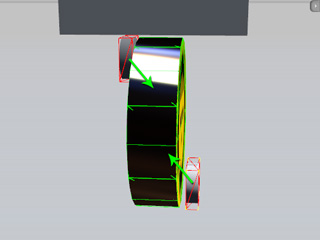
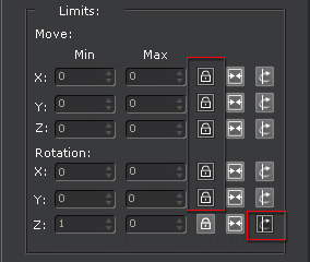
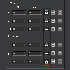
Adjust the settings in the Limits section as shown below:
|
|
|
The Local Z axes of the two cylinders are set free for them to rotating around.
|
-
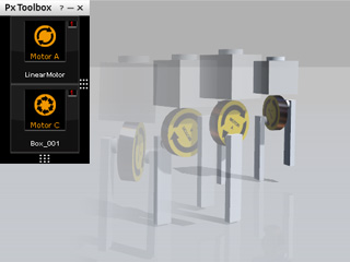
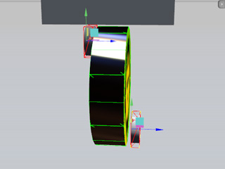
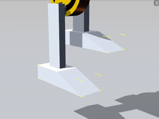
Add two more boxes and then transform them into pillar-shaped legs. Position them as shown in the illustration below (Also, switch to the
Local Move tool by pressing the W key to observe the directions of the pivots of the legs):
Fastening the Constraint Structure
-
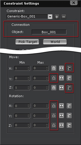
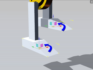
Set the legs as Dynamic rigid body and then apply Generic constraints to them with
the settings below in order to keep the legs from shaking.
|
-
Connect them to the Box so that they can rotate alone with the direction of the segway.
-
Set the (X, Y, Z) in the Move section
to (Free, Lock, Free) so that the legs can only move
along their Local X and Local Z axes.
-
Set the (X, Y, Z) in the Rotation section
to (Lock, Lock, Lock) so that the legs will be kept vertically straight at all times.
|
-
Select the two cylinder bolts, apply new Generic constraints to them and
individually take the legs as targets.
-
Set the specifications for the cylinder bolt generic constraints as in the illustration shown below:
|
-
Connect them to the Box so that they can rotate alone with the direction of the segway.
-
Set the (X, Y, Z) in the Move and Rotation sections
to (Lock, Lock, Lock) so that the bolts and the legs are tightly connected.
|
-
Click the play button on the control to begin simulation. The robot can then walk with a speed and direction controlled by you.
Adding Foots with Spring Constraints
After the legs are mounted, you may also optionally add feet to the legs with spring constraints to have a more detailed robotic structure.
-
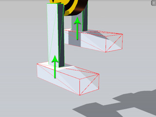
Go back to the start frame and add two arc props and position them under the legs.
-
Set them as Dynamic rigid bodies.
-
Because the pivots will be applied with Spring constraint later, you need to rotate the
Local X axes of the feet.
-
Apply Spring constraints to the feet and pick the legs as targets.
-
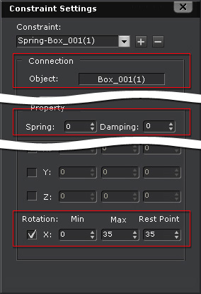
Set the spring settings as the illustration shown below:
|
-
The target objects are the boxes which act as the legs.
-
Decrease the Spring strength to
0 to stop the aftermath spring force from the feet.
-
Set the rotation range, (Min, Max), to
(0, 35).
-
Set the Rest Point to 35 so that each
time the legs raise, the toes will lift up
35 degrees.
|
-
Play to simulate the result and observe the robot walk on the floor with spring-loaded feet.